DTB 4824 RR

Температурный контроллер Delta с ПИД регулятором.48x24 mm, 2 релейных выхода 250VAC, 5A
развернуть ▼ свернуть ▲
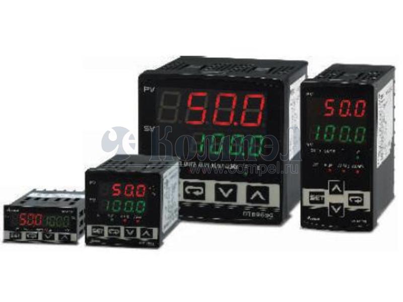
Файлы 1

показать свернуть
2006-12-19 5011628704-DBE4 http://www.delta.com.tw/industrialautomation/ Series Temperature Controller Instruction Sheet Thank you very much for purchasing DELTA B Series. Please read this instruction sheet before using your B series to ensure proper operation and please keep this instruction sheet handy for quick reference. Precautions DANGER! Caution! Electric Shock! 1. Do not touch the AC terminals while the power is supplied to the controller to prevent an electric shock. 2. Make sure power is disconnected while checking the unit inside. 3. The symbol indicates that this Delta B Series Temperature Controller is protected throughout by DOUBLE INSULATION or REINFORCED INSULATION (equivalent to Class II of IEC 536). WARNING! This controller is an open-type temperature controller. Make sure to evaluate any dangerous application in which a serious human injury or serious property damage may occur. 1. Always use recommended solder-less terminals: Fork terminal with isolation (M3 screw, width is 7.0mm (6.0mm for DTB 4824), hole diameter 3.2mm). Screw size: M3 x 6.5 (With 6.8 x 6.8 square washer). Screw size for DTB4824: M3 x 4.5 (With 6.0 x 6.0 square washer). Recommended tightening torque: 0.4 N.m (4kgf.cm). Applicable wire: Solid/twisted wire of 2 mm2, 12AWG to 24AWG. Please be sure to tighten them properly. 2. Do not allow dust or foreign objects to fall inside the controller to prevent it from malfunctioning. 3. Never modify or disassemble the controller. 4. Do not connect anything to the “No used” terminals. 5. Make sure all wires are connected to the correct polarity of terminals. 6. Do not install and/or use the controller in places subject to: • Dust or corrosive gases and liquid. • High humidity and high radiation. • Vibration and shock. • High voltage and high frequency 7. Must turn power off when wiring and changing a temperature sensor. 8. Be sure to use compensating wires that match the thermocouple types when extending or connecting the thermocouple wires. 9. Please use wires with resistance when extending or connecting a platinum resistance thermometer (RTD). 10. Please keep the wire as short as possible when wiring a platinum resistance thermometer (RTD) to the controller and please route power wires as far as possible from load wires to prevent interference and induced noise. 11. This controller is an open-type unit and must be placed in an enclosure away from high temperature, humidity, dripping water, corrosive materials, airborne dust and electric shock or vibration. 12. Please make sure power cables and signals from instruments are all installed properly before energizing the controller, otherwise serious damage may occur. 13. Please do not touch the terminals in the controller or try to repair the controller when power is applied to prevent an electric shock. 14. Wait at least one minute after power is disconnected to allow capacitors to discharge, and please do not touch any internal circuit within this period. 15. Do not use acid or alkaline liquids for cleaning. Please use a soft, dry cloth to clean the controller. 16. This instrument is not furnished with a power switch or fuse. Therefore, if a fuse or power switch is required, install the protection close to the instrument. Recommended fuse rating: Rated voltage 250 V, Rated current 1 A. Fuse type: Time-lag fuse 17. Note: This controller does not provide overcurrent protection. Use of this product requires that suitable overcurrent protection device(s) must be added to ensure compliance with all relevant electrical standards and codes. (Rated 250 V, 15 Amps max). A suitable disconnecting device should be provided near the controller in the end-use installation. PV Display : to display the process value or parameter type. SV Display : to display the set point, parameter operation read value, manipulated variable or set value of the parameter. AT : Auto-tuning LED, flashes when the Auto-tuning operation is ON. OUT1/OUT2 : Output LED , l ights when the output is ON. : Function key . Press this key to select the desired function mode and confirm a setting value. : Mode key. Press this key to set parameters within function mode. O O C, F : Temperature unit LED .OC : Celsius OF : Fahrenheit ALM1 ~ ALM3 : Alarm output LED, lights when ALM1/ALM2/ALM3 is ON. : Down key . Press this key to decrease values displayed on the SV display. Hold down this key to speed up the decrements. : Up key . Press this key to increase values displayed on the SV display. Hold down this key to speed up the incremental action. Ordering Information DTB Series 12 3 4 5 6 7 Panel Size (W×H) 1st Output Group Selection 2nd Output Group Selection EVENT Inputs / CT function (Optional) 7 DTB: Delta B Series Temperature Controller 4824: 1/32 DIN W48 × H24mm 4896: 1/8 DIN W48 × H96mm 4848: 1/16 DIN W48 × H48mm 9696: 1/4 DIN W96 × H96mm R: Relay output, SPDT (SPST: 1/16 DIN and 1/32 DIN size), 250VAC, 5A V: Voltage pulse output, 14V +10﹪~ -20﹪(Max. 40mA) C: DC current output , 4 ~ 20m A L: Linear voltage output, 0~5V, 0~10Vdc R: Relay output, SPDT (SPST: 1/16 DIN and 1/32 DIN size), 250VAC, 5A V: Voltage pulse output, 14V +10﹪~ -20﹪(Max. 40mA) None: No EVENT input , No CT (Current transformer) E: EVENT input is provided, No CT (Current transformer) T: CT (Current transformer) is provided, No EVENT input V: Valve control. Note 1: DTB4824 series: no optional function provided and no extra alarm output supported, but user can set 2nd output as alarm mode. Note 2: DTB4848 series: only one alarm output when optional function supported, but user can set 2nd output as 2nd alarm output. Note 3: “Valve control” with feedback selection is only available for DTB4896RRV, DTB9696RRV. Specifications Input Voltage Operation Voltage Range Power Consumption Memory Protection Display Method Sensor Type Control Mode Control Output Display Accuracy Sampling Rate RS-485 Communication Vibration Resistance Shock Resistance o 0 C to +50 C o o -20 C to +65 C 2000m or less 35% to 80% (non-condensing) 100 to 240VAC 50/60Hz 85% to 110% of rated voltage 5VA max. EEPROM 4K bit (non-volatile memory (number of writes: 100,000) 2 line x 4 character 7-segment LED display Process value(PV): Red color, Set point(SV): Green color Thermocouple: K, J, T, E, N, R, S, B, L, U, TXK 3-wire Platinum RTD: Pt100, JPt100 Analog input: 0 ~ 5V, 0 ~ 10V, 0 ~ 20 m A, 4 ~ 20 m A, 0 ~ 50mV PID, ON/OFF, Manual or PID program control (Ramp/Soak control) Relay output: SPDT (SPST: 1/16 DIN and 1/32 DIN size), Max. load 250VAC, 5A resistive load Voltage pulse output: DC 14V, Max. output current 40mA Current output: DC 4 ~ 20m A output (Load resistance: Max. 600Ω) Linear voltage output: 0 ~ 10V 0 or 1 digit to the right of the decimal point (selectable) Analog input: 150 msec/ per scan Thermocouple or Platinum RTD: 400 msec/per scan MODBUS ASCII / RTU communication protocol 2 10 to 55Hz, 10m/s for 10min, each in X, Y and Z directions 2 Max. 300m/ s , 3 times in each 3 axes, 6 directions Upper-limit regulation of valve output with feedback to controller. (Display when valve signal feedback function is ON) Press Temperature Sensor Type & Temperature Range Input Temperature Sensor Type 0 ~ 50mV Analog Input Register Value 17 LED Display Temperature Range -999 ~ 9999 16 -999 ~ 9999 0 ~ 20mA Analog Input 15 -999 ~ 9999 0V ~ 10V Analog Input 14 -999 ~ 9999 0V ~ 5V Analog Input 13 -999 ~ 9999 4 ~ 20mA Analog Input Platinum Resistance (Pt100) o -200 ~ 600 C 12 o Platinum Resistance (JPt100) 11 -20 ~ 400 C Thermocouple TXK type 10 -200 ~ 800 C Thermocouple U type 9 -200 ~ 500 C o o o Thermocouple L type 8 -200 ~ 850 C Thermocouple B type 7 100 ~ 1800 C Thermocouple S type o o 5 0 ~ 1700 C Thermocouple N type 4 -200 ~ 1300 C 3 0 ~ 600 C 2 -200 ~ 400 C Press Stop bit setting Press Press to return to auto-tuning mode 1 Scale = 2.8uA = 1.3mV for tuning output value PID mode selection: any one of 4 groups PID modes (n = 0 ~ 3) can be selected. When n = 4, program will automatically select 1 group PID that is most useful for target temperature. Select n=0~4 to decide PID mode. key less than 3 sec Operation Mode Press Use key to set temperature set point Press Press Decimal point position selection (except for B, S, R type, all the other types can be set) Press Cooling hystereisis setting (Set in ON/OFF control mode) Upper-limit alarm 1 (This parameter is available only when ALA1 function enables) Press (This parameter is available only when ALA1 function enables) Press Upper-limit alarm 2 (This parameter is available only when ALA2 function enables) Press P value of 1st & 2nd output group during dual loop output control P value of 2nd output group = (P value of 1st output group) x (This parameter is available only when ALA2 function enables) Set input type Press Set temperature unit Set upper-limit of temperature range Press Set lower-limit of temperature range Press Select control mode (See "Pattern and set Editing selection" for detail) Press Select heating/cooling control or dual loop output control Press Alarm 1 mode setting Press Lower-limit alarm 2 Alarm 2 mode setting Press Press Press Dead Band (Set in Dual Loop output control mode) Press Switch setting for feedback signal of valve. (Display when valve control is ON) Press Automatically regulate feedback value. (Display when valve control is ON) Press Time setting for valve from full close to full open. (Display when valve control is ON) Press Valve Dead Band setting. (Display when valve control is ON) Press Press Pattern and step editing selection: edit Upper-limit alarm 3 (This parameter is available only when ALA3 function enables) Press Alarm 3 mode setting Press Lower-limit alarm 3 (This parameter is available only when ALA3 function enables) Press Set system alarm Press Communication write function enable/disable Setting lock mode Press Display and adjust output value of 1st output group (Display in PID control mode and manual RUN mode) Press Display and adjust output value of 2nd output group (Display in dual loop PID control mode and manual RUN mode) Press Press ASCII, RTU communication format selection Press Communication address setting Press Select desired editing pattern number select OFF select number in Switch to and continue setting back to PID deviation setting Press back to PID deviation setting parameter. The following display is the example operation of pattern No. 0. Select actual step No. when program control is executing Edit temperature of step No. 0 of pattern No. 0 Press Press Edit time of step No. 0 of pattern No. 0, unit is hh.mm Exit pattern and step editing selection Set additional execution cycle number(0 to 99) Press Press Set step No. 07 in order Edit temperature of step No. 7 of pattern No. 0 Press Set link pattern, OFF indicates the program end Press mode to return pattern No. editing Edit time of step No. 7 of pattern No. 0, unit is hh.mm Press to set actual step No. Dual Loop Output Control (Heating/Cooling Control) Initial Setting Mode Initial Setting Mode Lower-limit alarm 1 Press Control cycle setting of 2nd output group (Set in PID control and Dual Loop output control mode) key Press Press Press Ti setting: n=3. Press Td setting: n=3.Press Press Heating hystereisis setting Ti setting: n=0. Press Integral deviation setting: n=3. AT setting. do not display when analog input Start pattern setting (PID program control and Time setting. (Set in ON/OFF control mode) Heating/Cooling or control cycle setting (Set in PID control mode) Press Control setting RUN or STOP Press Press key more than 3 sec Operation Mode (Set in PID control and RUN mode) PD control offset setting (When PID control is ON and Ti=0, set the value of PdoF. Press Proportion band setting: n=3. Press Integral deviation setting: n=0. AT setting. Press Press Proportion band setting: n=0. Press o -100 ~ 1200 C There are three modes of operation: operation, regulation and initial setting. When power is applied, controller gets into key to switch to regulation mode. If the key is pressed for more than 3 seconds, the operation mode. Press the key while in the regulation mode or initial setting mode, controller will switch to the initial setting mode. Pressing the forces the controller to return to the operation mode. PV/SV: Sets the temperature set point and displays the temperature keys to set the temperature set point. process value. Use Setting method: While in any function mode, press the key to select the desired function and use the keys to key to save the changes. The next flow chart shows how to switch for settings and internal change settings. Press functions: 4 groups PID modes (n=0~3). When n=4, PID control is auto regulated. PID setting: n=3.Press Td setting: n=0.Press Operation Regulation Mode PID setting: n=0.Press 0~3 groups PID Press o Note 2: (Operation mode) must be set if user wish to specify decimal point position. Except for the thermocouple B, S, R type, the decimal point positions of all the other thermocouple type input sensors can be set. The default range of analog input is -999 ~ 9999. For example, when a 0 ~ 20mA analog input is selected as the input temperature sensor type, -999 indicates 0mA and 9999 indicates 20mA. If change the input range to 0 ~ 2000, then 0 indicates 0mA and 2000 indicates 20mA. One display scale is equal to 0.01mA. key to return input type setting Regulate lower-limit of analog output value (The setting display when analog output) o 1 Press Parity bit setting Press Regulate upper-limit of analog output value (The setting display when analog output) Press -200 ~ 1300 C Thermocouple K type 0 Note 1: An internal 249Ω precision resistor for the current input is built-in, please refer to the item “How To Set Up Current Input”. Regulation Mode Data length setting Press DA value feedback of valve. (Display when valve feedback function is ON) Press Back to target temperature o Thermocouple T type Press Communication baud rate setting Press o Thermocouple E type Thermocouple J type In case of using an external CT, the controller displays the current value being measured by CT, if the control output is ON to return to set target temperature Valve output with feedback. (Display when valve feedback function is ON) Press Regulate temperature deviation value 0 ~ 1700 C Thermocouple R type Press Lower-limit regulation of valve output with feedback to controller. (Display when valve signal feedback function is ON) Press o 6 Auto-tuning Display, LED & Pushbuttons DTB 1 2 3 4 5 6 o Ambient Temperature Storage Temperature Altitude Relative Humidity Temperature control can be achieved either by heating or cooling. In DTB series, heating and cooling can be operated simultaneously (Dual Loop output control) to perform temperature control. When Dual Loop output control are used, two control outputs must be connected to the heating and cooling devices. Please refer to the following for the operation: : This parameter is used to select heating or cooling action if operate either heating or cooling function in this controller. When selecting , 1st output group is heating (reverse) control, and when selecting , 1st output group is cooling (forward) control. At this moment, 2nd output group is regarded as an alarm output. If user select or , it indicates that user can operate Dual Loop output control function in this controller. When selecting , 1st output group is heating (reverse) control and 2nd output group is cooling (forward) control. When selecting , 1st output group is cooling (forward) control and 2nd output group is heating (reverse) control. Dead band Heating hysteresis Cooling hysteresis ON Heating Cooling OFF PV Set point Figure 1. Output operation of ON/OFF control during dual loop output control Dead band: dead band width=positive Output Heating Cooling PV 0 Set point Figure 2. PID control, Dead Band is positive In DTB series, P (Proportional Band), I(Integral Time) and D(Derivative Time) parameters are automatically set by using the Auto-tuning (AT) function. Dead band: dead Output band width=negative : This parameter is for the control mode that must be Dual Loop output control with PID control method configured. The value of P, I and D of 1st output group can be set immediately. The P value of 2nd output group is equal to (P value of 1st output group) x Heating Cooling PV and the value of I and D of 2nd output group are the same as the 0 Set point value of I and D of 1st output group. Figure 3. PID control, Dead Band is negative : Dead Band, shown as the following figure 1, 2 and 3. This parameter sets an area in which the heating and cooling control output is 0 centering around the set point in a Dual Loop output control mode. : Settings lock. To avoid incorrect operation, two key lock functions are provided. : Lock 1 can lock all settings. All parameters and temperature settings can be locked to disable changes. : Lock 2 can lock settings except the SV (Set point) value. All parameters and temperature settings can be locked with the exception of the SV value. Press and key simultaneously, the “Lock” status can be released. Alarm Outputs There are up to three groups of alarm outputs and each group allows thirteen alarm types in the initial setting mode. The alarm output is activated whenever the process temperature value (PV) is getting higher or lower than the set point of alarm limit. Set Value 0 2 Alarm Type Alarm function disabled Deviation upper- and lower-limit: This alarm output operates when PV value is higher than the setting value SV+(AL-H) or lower than the setting value SV-(AL-L). Deviation upper-limit: This alarm output operates when PV value is higher than the setting value SV+(AL-H). 3 Deviation lower-limit: This alarm output operates when PV value is lower than the setting value SV-(AL-L). 1 Alarm Output Operation Output is OFF ON OFF SV-(AL-L) SV SV+(AL-H) SV SV+(AL-H) ON OFF ON OFF SV-(AL-L) SV PDF
Документация на DTB 4848 VR 

Microsoft Word - 5011628704-DBE4.doc

Дата модификации: 27.12.2006

Размер: 1.2 Мб

2 стр.

    Внимание! Точность указанного на сайте описания товара не может быть гарантирована. Для получения более полной и точной информации о товаре смотрите техническое описание (Datasheet) на сайте производителя.